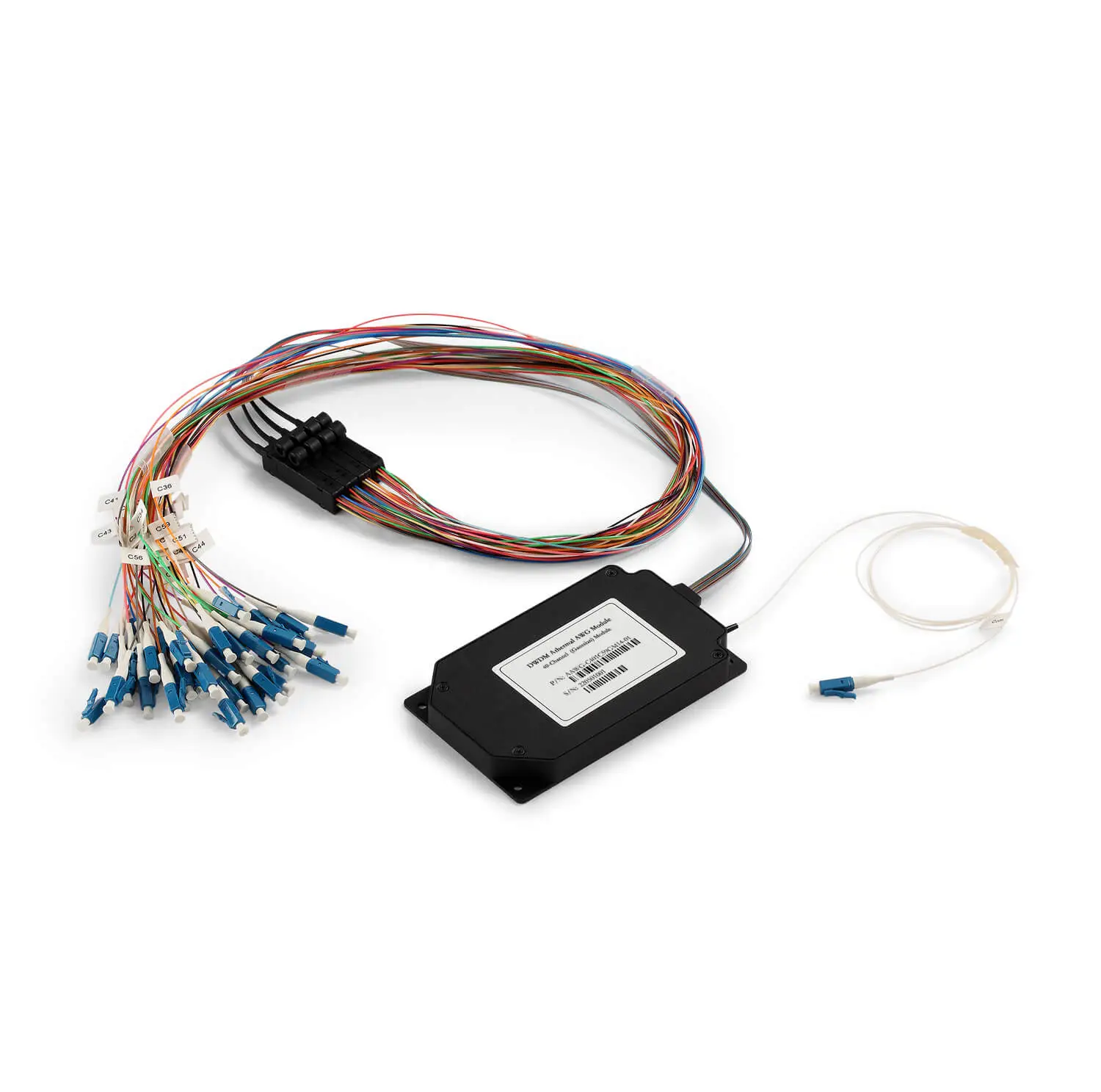
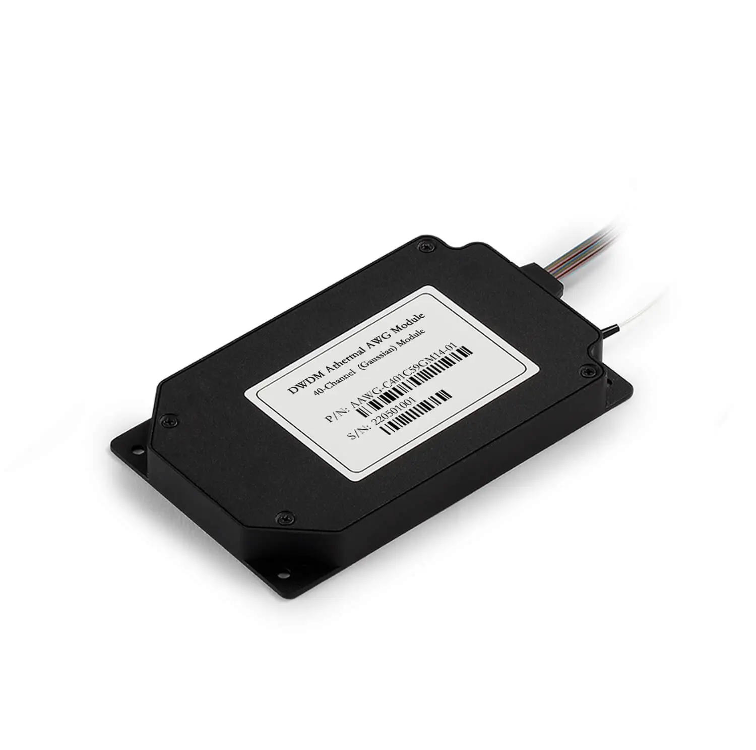
The 40-Channel AAWG Module is an advanced wavelength division multiplexing solution for DWDM systems, providing a higher channel count and greater bandwidth capacity for modern optical communication networks. This module, built on state-of-the-art silicon silica planar waveguide technology, offers excellent wavelength selectivity and low insertion loss while maintaining minimal footprint and energy efficiency. Its athermal design ensures stable operation without the need for active thermal control, making it ideal for cost-effective and scalable network expansion.
| Parameters | Conditions | Specifications | Units |
| Min | Max |
|
| Operating Temperature | Non-Condensing Environment | -5 | 65 | ℃ |
| Operating Humidity |
| 5 | 95 | %RH |
| Storage Temperature |
| -40 | 85 | ℃ |
| Storage Humidity |
| 5 | 95 | %RH |
| Maximum Optical Power | All Mux/Demux Input Ports at the same time, Continuous |
| 300 | mW |
Note:
Parameters are specified for the whole passband over all polarization states and operating temperature range

 Fiber Optic Flex Circuit (FOFC)
Advanced Simulation & Optimization, High Positioning Accuracy, Flexible Customization, Rigorous Reliability Testing
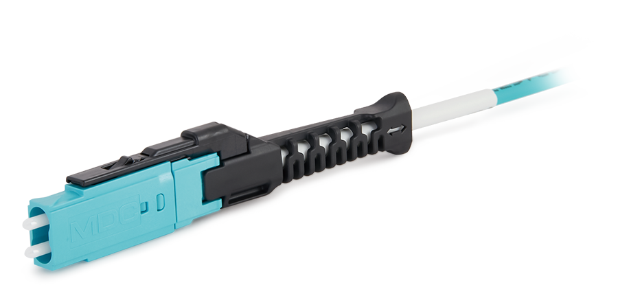
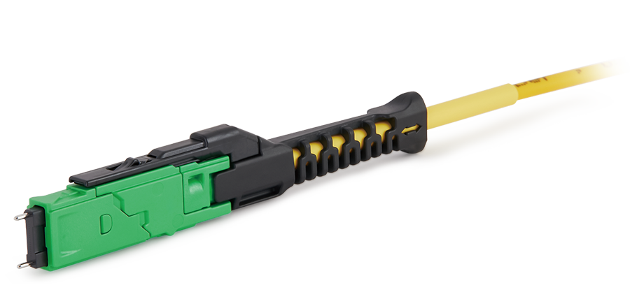
 MDC Solution
US Conec's MDC connector is a Very Small Form Factor (VSFF) duplex optical connector, expertly designed for terminating single-mode and multimode fiber cables with diameters up to 2.0mm.
 MMC Solution
US Conec's Very Small Form Factor (VSFF) multi-fiber optical connector that redefines high-density connectivity with its cutting-edge TMT ferrule technology and intuitive Direct-Conec™ push-pull boot design.
 EN
EN
 jp
jp  fr
fr  es
es  it
it  ru
ru  pt
pt  ar
ar  el
el  nl
nl 


_and_High-Reflection_(HR)_Optical_Coatings.webp)