In order to make the end faces of the two optical fibers better contact, the ferrule end faces of the fiber jumpers are usually ground into different structures. Common grinding methods are: PC, APC, UPC. PC/APC/UPC represents the front face structure of the ceramic ferrule.
Ⅰ. The end face grinding angle of the optical fiber jumper is different
1. PC is Physical Contact, physical contact. PC is micro-spherical grinding and polishing, the surface of the optical fiber ferrule is ground into a slight spherical surface, and the fiber core is located at the highest point of bending, which can effectively reduce the air gap between the fiber components and make the two fiber end faces reach physical contact.
2. UPC (Ultra Physical Contact), ultra-physical end face. The end face of the UPC connector is not completely flat, but has a slight curvature for more precise mating. UPC is based on PC with more optimized end surface polishing and surface finish, and the end surface looks more dome-shaped.
3. APC (Angled Physical Contact) is called inclined plane physical contact, and the fiber end face is usually ground into an 8° inclined plane. The 8° angled bevel allows for tighter fiber endfaces and provides better connection performance by reflecting light through its bevel angle to the cladding rather than directly back to the source.
Ⅱ. The color of the fiber jumper is different
APC connectors are usually green and UPC/PC connectors are blue.
Ⅲ. Return loss and insertion loss of fiber jumper
Different grinding methods determine the optical fiber transmission quality, mainly reflected in return loss and insertion loss. Insertion Loss (Insertion Loss) refers to the signal loss through the connector.
In general, the typical insertion loss of PC, UPC and APC connectors should be less than 0.3dB. Compared to APC connectors, UPC/PC connectors are generally easier to achieve low insertion loss due to the smaller air gap. Insertion loss can also be caused by dust particles between the connector end faces.
Return Loss (Return Loss), also known as reflection loss, is a parameter that represents the reflection performance of a signal, usually represented by a negative dB value. The higher the value of the parameter, the better. The end face of APC connectors is bevel polished, so the return loss of APC connectors is usually better than that of UPC connectors.
Under normal circumstances, the return loss of the optical fiber patch cord using the PC grinding method is -40dB. UPC return loss is higher than PC, generally -55dB (or even higher). The APC industry standard return loss is -65dB. When using a UPC connector, some of the reflected light will be emitted back to the light source, while the beveled end face of the APC connector will reflect some of the reflected light to the cladding at an angle, thereby reducing more reflected light back to the light source. This is the main factor that causes the return loss to be different.
Ⅳ. Application scenarios of optical fiber jumpers
PC is the most common grinding method for fiber optic connectors and is widely used in telecom operator equipment. UPC is usually used in Ethernet network equipment (such as ODF fiber optic distribution frame, media converter and fiber optic switch, etc.), digital, cable TV and telephone systems. APCs are generally used in high wavelength range optical RF applications such as CATV, but also in optical passive applications such as PON network structures or passive optical local area networks.
The connector connection needs to have the same end face structure. For example, the end face of the APC is ground into an 8-degree angle, and the APC cannot be combined with the UPC, which will reduce the performance of the connector. However, the fiber end faces of PC and UPC are both flat, and the difference lies in the quality of grinding. Therefore, the mixed connection of PC and UPC will not cause permanent physical damage to the connector.

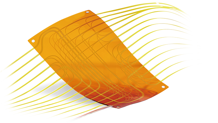 Fiber Optic Flex Circuit (FOFC)
Advanced Simulation & Optimization, High Positioning Accuracy, Flexible Customization, Rigorous Reliability Testing
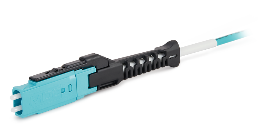 MDC Solution
US Conec's MDC connector is a Very Small Form Factor (VSFF) duplex optical connector, expertly designed for terminating single-mode and multimode fiber cables with diameters up to 2.0mm.
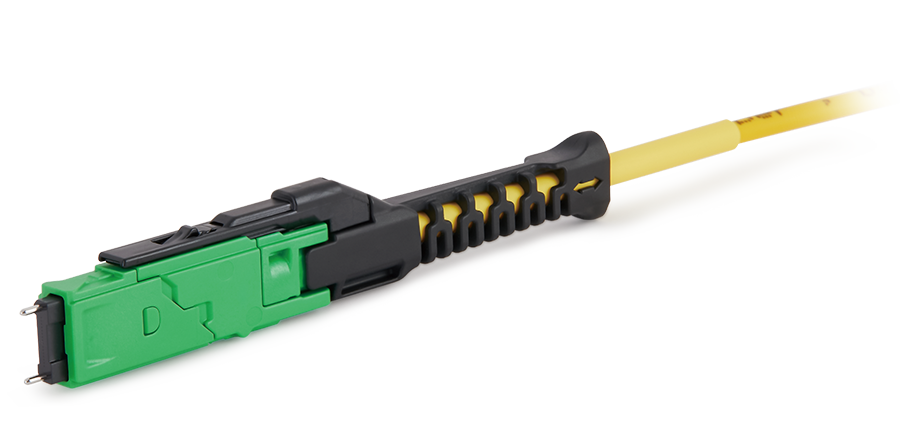 MMC Solution
US Conec's Very Small Form Factor (VSFF) multi-fiber optical connector that redefines high-density connectivity with its cutting-edge TMT ferrule technology and intuitive Direct-Conec™ push-pull boot design.
 EN
EN
 jp
jp  fr
fr  es
es  it
it  ru
ru  pt
pt  ar
ar  el
el  nl
nl 

_and_High-Reflection_(HR)_Optical_Coatings.webp)
