Quick answer
MPO and MTP connectors consolidate numerous fibers using high-density push-pull connections. Five variables relative to the link and the transceiver must be specified to guarantee correct specification: how many fibers, gender, type (A/B/C) of polarity, type of polish, and the level of insertion loss.
Connectors between transceivers and fiber plant are called MPO connectors, and a variant of this connector, the MTP connector, is protected by patent. MPO/MTP connectors facilitate high-speed connections and bundle several fibers together as compared to individual fibers connected using LC or SC connectors. Moreover, MPO/MTP connectors simplify connections by using a push-pull mechanism as opposed to individual fiber connectors that require alignment. Given the high-speed nature of connections and the densification of data center interconnects, specifying MPO/MTP connectors has become commonplace. Each specification, however, needs to consider fiber count, polarity, type of polish, and insertion loss. A specification that fails to take any one of these factors into consideration will result in complete failure of the connection, despite individual components of the specification (fiber, connectors, and cleaves) passing tests.
What Is an MPO/MTP Connector?
MPO (Multi-fiber Push On) is the base connector standard; MTP® is US Conec's branded MPO connector solution, designed with enhanced mechanical features and performance, with a removable housing, stronger spring design and tighter guide-pin tolerances. The two connector types are interoperable but not mechanically identical — T&S covers the mechanical and reliability differences between MTP and MPO connectors in a dedicated article. This guide focuses on the bigger picture: how to specify an MPO/MTP link end to end.

Fiber Count Options
MPO/MTP connectors are available in several fiber counts — Common configurations include 8F, 12F, 16F, 24F, 32F and 36F, with other fiber counts available depending on connector and application requirements. The count a given project needs is driven primarily by the transceiver's port interface and the breakout configuration on each end, not by the cable in isolation. Higher fiber counts pack more channels into a single connector but also raise the stakes of a fiber-count mismatch, so confirming the exact count against the transceiver and system vendor's documentation is the first step before specifying anything else — including polarity, which is a separate decision covered next.
Polarity: Type A, B and C
Polarity — how fiber positions are mapped from one end of an MPO link to the other — is a separate design decision and one of the most common sources of confusion in MPO connector selection.
A given fiber count does not determine a single “correct” polarity type.
Select polarity based on the complete link design, including the transceiver pinout, trunk cable, cassettes and patch cords — fiber count alone does not determine polarity. A mismatched polarity method is one of the most common causes of failed link tests in a new MPO deployment: it typically shows up as a failed transmit/receive continuity test on the affected channel, even though every connector mates cleanly and passes a visual inspection. Confirming the A/B/C method against the equipment vendor's documentation — not inferring it from the connector's fiber count — is the single most important step in an MPO/MTP spec.
Polish Type and Fiber Mode
MPO/MTP connectors come in two polish types:
APC (Angled Physical Contact) — an 8° angled endface designed to reduce back-reflection and improve return loss, commonly used in single-mode applications.
PC (Physical Contact) — a flat endface, commonly used for multimode applications.
These are common conventions, not fixed rules — always confirm the required polish type against the transceiver/system interface specification rather than assuming it from fiber mode alone. Single-mode MPO/MTP assemblies may use G.657A1/A2 or other specified single-mode fiber types; multimode versions commonly use OM3, OM4 or OM5, depending on the reach and speed required. T&S covers why polish type matters — and how APC differs from UPC — in a dedicated PC vs. UPC vs. APC ferrule polish guide.

MPO Insertion Loss Grades
T&S's MPO/MTP cable assemblies are published in two insertion loss grades — ELITE (also labeled “Low-Loss” on some product lines) and STANDARD — and the maximum allowed loss differs by fiber mode, not just by grade:
Figures per mating pair, per T&S's published MPO/MTP cable assembly and trunk cable specifications as of this review; confirm against the current datasheet before using in a project's loss budget, since published figures can change between product revisions.
Note that STANDARD-grade maximum loss is not one number across the board — single-mode STANDARD (≤0.75dB max) allows more loss per connection than multimode STANDARD (≤0.60dB max). Mixing up the two when budgeting a single-mode link is an easy way to under-estimate total link loss. On a short single-connector jumper, the grade difference barely matters. On a structured link with multiple MPO mating points — trunk to cassette to patch cord — insertion loss stacks up fast, and the grade a buyer chooses can have a direct impact on how much margin remains in the overall optical loss budget, especially at 400G and 800G where link budgets are already tight.
Worked Example: Estimating Insertion Loss for a 16F Trunk-to-Cassette Link
The following is an illustrative insertion-loss calculation for a hypothetical three-mating-point link, not a validated field deployment. Treat it as a worksheet template — confirm every real component's specification against its datasheet, and add fiber attenuation and design margin before using it as an actual link budget.
Link map (3 MPO mating points)
Switch (400G port, 16F MPO interface, Type B polarity — confirm against the actual switch/transceiver datasheet)
→ MPO trunk cable (16F, single-mode, APC) [mating point 1] → Cassette A (16F MPO in)
→ MPO trunk cable (16F, single-mode, APC) [mating point 2] → Cassette B (16F MPO in / breakout side per design)
→ MPO patch cord (16F, single-mode, APC) [mating point 3] → Transceiver (400G port, 16F MPO interface)
Configuration assumptions for this example:
Fiber mode: single-mode, APC polish, G657A1/A2 fiber
Fiber count: 16F; polarity was set to Type B for this specific link design (its transceiver pinout and cassette layout) — not because 16F requires Type B
Mating points: 3 (switch-to-trunk, trunk-to-cassette, cassette-to-patch cord)
Per-mating-point insertion loss subtotal at STANDARD grade, single-mode (≤0.75dB max per point, per T&S's published spec): up to 2.25dB
Per-mating-point insertion loss subtotal at ELITE grade, single-mode (≤0.35dB max per point, per T&S's published spec): up to 1.05dB
These are connector mating-loss subtotals only — not a complete link loss budget. A full budget also needs: fiber attenuation over the actual cable length (single-mode fiber typically runs around 0.35–0.4dB/km at 1310nm and somewhat lower, roughly 0.2–0.35dB/km, at 1550nm — check the specific fiber grade's datasheet), any splice loss, and a design margin (commonly 1–3dB), before comparing the total against the transceiver's optical budget. Even so, the 1.20dB gap between the two grade subtotals here is meaningful once folded into the rest of the budget — which is why grade selection is a link-level decision, not a per-cable one.
Matching MPO/MTP Connectors to Network Speed
Fiber count and transceiver interface need to line up — and a couple of these are breakout configurations rather than native fiber counts, which is worth distinguishing:
40GBASE-SR4: typically uses a 12-fiber MPO interface, with 8 active fibers (4 Tx + 4 Rx). (4 transmit + 4 receive; the remaining 4 unused in a standard 40GBASE-SR4 configuration)
10G (via breakout): typically four 10G links can be broken out from a 40G SR4 QSFP+ port using an MPO-to-4×LC harness.
100G: MPO-based configurations include SR4 and DR applications, typically using MPO-12 interfaces; other 100G optics such as LR4 and CWDM4 use duplex LC.
400G: MPO interfaces vary by optical technology. For example, 400G DR4 uses 8 active fibers in an MPO-12/APC interface, while 400G SR8 uses 16 fibers in an MPO-16/APC interface. Other 400G optics, such as FR4 and LR4, use duplex LC interfaces. Always confirm the exact transceiver interface before specifying the cable.
800G: MPO/MTP interfaces vary by transceiver architecture, with configurations including MPO-16 and dual MPO-12 interfaces. Confirm the exact connector and fiber configuration against the transceiver datasheet.
Migrating between speeds usually means re-thinking the MPO/MTP layer, not just swapping transceivers — which is why planning the cabling architecture with headroom for the next speed step is worth the upfront cost.

Cable Types and Configurations
Beyond a straight trunk cable, MPO/MTP infrastructure includes several configurations built for different points in the network:
MPO trunk cable / MTP cable — point-to-point high-count backbone runs
MPO harness cable — breaks out an MPO trunk into individual LC/SC connectors
MPO Bundle cables — combine multiple MPO connectors (e.g. 8F×24, 12F×4, 12F×8, 24F×2) for switch-to-server fan-out
Cassette modules — rack-mount interconnect points between the MPO trunk cable and the MPO patch cord / MTP patch cord layer
Jacket material (Riser/OFNR, Plenum/OFNP, or LSZH) needs to match the cable pathway's applicable fire and electrical code. In North America, plenum spaces typically require an OFNP-rated (optical-fiber, nonconductive, plenum) jacket under NEC Article 770 (NFPA 70); LSZH is a separate low-smoke, halogen-free property specified for its own reasons — common outside North America and in enclosed spaces with strict smoke-toxicity requirements — rather than an automatic substitute for a plenum rating. Confirm the exact jacket requirement against the local code and the building's authority having jurisdiction (AHJ) before ordering.
When to Use LC/SC Instead of MPO/MTP
MPO/MTP isn't the right choice for every link. For low fiber-count runs — a single switch-to-switch uplink, or a point-to-point connection that doesn't need to scale beyond a few fibers — simplex or duplex LC/SC connectors are simpler to install and cheaper per connection. They generally require simpler polarity planning than MPO/MTP links, although Tx/Rx assignment still needs to be confirmed — polarity planning is simpler with LC/SC, not eliminated. MPO/MTP earns its added complexity specifically when fiber count climbs into double digits per link and cassette-based breakout becomes worth the upfront design work.
MPO Connector Selection Checklist
Before placing an order, run each of the following against the equipment vendor's documentation — treat it as a specification audit, not a formality:
Mode & fiber type match — confirm fiber mode (SM or MM) and fiber type (G657A1/A2, OM3/OM4/OM5) against the transceiver's specification
Polarity method confirmation — confirm the A/B/C polarity method against the complete link design (transceiver pinout, trunk, cassettes, patch cords); never assume it from the connector's fiber count alone
Insertion loss grade vs. mating-point count — total the actual per-datasheet insertion loss across every mating point in the link (using the correct single-mode or multimode threshold for the grade), then choose ELITE or STANDARD against that total, not by cable price alone
Jacket rating vs. installation environment — confirm OFNR/OFNP/LSZH jacket rating against the local fire/electrical code for where the cable will actually run
Common MPO/MTP Specification Mistakes
Mistake | Consequence | Fix |
|---|
Assumed polarity from fiber count or connector appearance instead of confirming against the full link design | Failed transmit/receive continuity after installation | Confirm the A/B/C polarity method against the transceiver pinout, trunk, cassettes and patch cords before ordering |
Chose grade by cable price alone, or applied the multimode STANDARD threshold to a single-mode link | Link exceeded the transceiver's loss budget once multiple mating points were added | Total each mating point's actual per-datasheet insertion loss, using the correct single-mode or multimode threshold, before choosing a grade |
Used a riser-rated jacket in a plenum space, or assumed LSZH automatically satisfies a plenum rating | Fire code non-compliance, failed inspection | Confirm jacket rating (OFNR/OFNP/LSZH) against the local code and the AHJ, not by assumption |
Treated MTP branding itself as a performance spec | Ordered connector didn't meet the required insertion loss grade | Check the datasheet's grade (ELITE/STANDARD) and test condition, not just the connector name |
FAQ
Q: Can ELITE and STANDARD grade MPO/MTP cable be mixed in the same link?
A: Technically yes, but each mating point should be budgeted at its own actual specified grade and fiber mode rather than assumed uniformly — T&S's own published STANDARD-grade maximum is ≤0.75dB for single-mode versus ≤0.60dB for multimode, so “STANDARD” alone isn't a single number. The accurate approach is to sum each connection point's actual per-datasheet insertion loss, for the correct fiber mode, rather than applying one blanket figure across the whole link.
Q: Does MTP branding guarantee better performance than a generic MPO connector?
A: Not automatically. MTP® is a trademark for a specific mechanical design from US Conec, not a performance guarantee on its own. Insertion loss grade and manufacturing quality control matter more than the branding alone — confirm the actual specification sheet, not just the connector name.
Q: What happens if the polarity type doesn't match between the trunk and the cassette?
A: The link will typically fail transmit/receive continuity on that channel, even though the connectors physically mate without issue. This is why polarity should be confirmed against the complete link design before ordering — never assumed from the connector's fiber count or gender alone.
Procurement Parameter Checklist
Filling in this table before contacting T&S shortens the configuration-review cycle:
Parameter | Your Requirement |
|---|
Fiber count (8F/12F/16F/24F/32F/36F) |
|
Connector gender (male/female) |
|
Polarity method (Type A/B/C) |
|
Polish / endface (PC/APC) |
|
Fiber mode (single-mode / multimode) |
|
Cable length |
|
Jacket type (OFNR/OFNP/LSZH) |
|
Insertion loss grade (ELITE/STANDARD) |
|
Quantity |
|
Get a Configuration Reviewed
Send T&S your transceiver model, required fiber count, cable length, polarity and jacket requirements — the table above covers the essentials. T&S's engineering team can review the configuration and recommend a suitable MPO/MTP cable assembly before you place an order.
Conclusion
MPO/MTP connectivity is what makes high-density, high-speed data center cabling manageable — but only when fiber count, polarity, polish and insertion loss grade are specified correctly, and polarity is confirmed against the complete link design rather than assumed from fiber count alone. T&S supplies MPO trunk cable, MPO harness cable, hydra and bundle cable assemblies across 8F–36F configurations, in both ELITE and STANDARD insertion loss grades, for 10G through 800G networks.
Explore T&S's: MPO cable and MTP cable assemblies
Related reading — differences between MTP and MPO connectors
Related reading — types, male/female and classification of MPO/MTP patch cords
References
MPO/MTP polarity methods (Type A/B/C) are defined under ANSI/TIA-568.3-E (published September 2022), the current edition of the commercial building telecommunications cabling standard covering optical fiber connector polarity for multi-fiber connectors. Insertion-loss grade thresholds (ELITE/Low-Loss ≤0.35dB max, STANDARD ≤0.75dB max single-mode / ≤0.60dB max multimode) reflect T&S’s published MPO/MTP cable assembly and trunk cable specifications as of this review—confirm against the current datasheet and test report before using these figures in a project’s loss budget, since published specifications can change between product revisions. Jacket-rating requirements (OFNR/OFNP/LSZH) should be confirmed against the applicable local electrical and fire code, such as NEC Article 770 in North America, rather than assumed from this guide alone.
 EN
 jp
 fr
 es
 it
 ru
 pt
 ar
 el
 nl

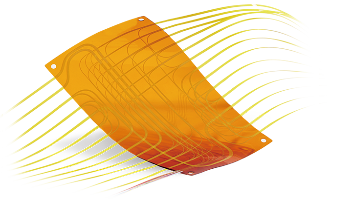 Fiber Optic Flex Circuit (FOFC)
Advanced Simulation & Optimization, High Positioning Accuracy, Flexible Customization, Rigorous Reliability Testing
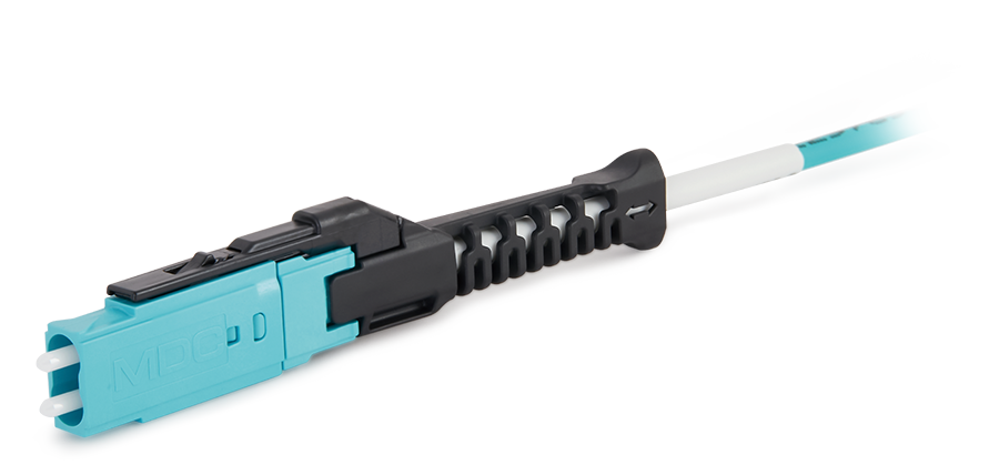 MDC Solution
US Conec's MDC connector is a Very Small Form Factor (VSFF) duplex optical connector, expertly designed for terminating single-mode and multimode fiber cables with diameters up to 2.0mm.
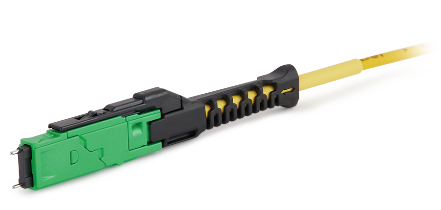 MMC Solution
Explore MMC cable and connector solutions for high-speed data centers, AI and HPC, including custom assemblies for 400G/800G network applications.